Video Settings

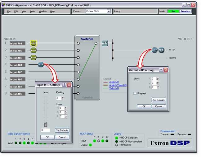
You can adjust video settings for the MLS 608 D Series in the Video I/O workspace. To open this workspace, select Video I/O from the View menu, press <F4>, or click Video I/O in the Legend section of another workspace. See the Workspaces Overview section and the Switcher Operation section for more information.

RGB Delay

During switching, the MTP video output can be set to switch the input sync source first, followed by the RGB portion of the signal. This brief delay allows the display to adjust to the new sync signal before sending the picture, providing a glitch-free switch. RGB delay can be set from 0 to 5 seconds in 0.5-second increments.

To set RGB delay:

  1. In the Video I/O workspace, double-click the RGB DLY (RGB Delay) block. Alternatively, select the block and press <Enter>. The RGB Delay dialog box opens with a slider to set the delay time.

  2. Click and drag the slider handle to the right to set the time. Alternatively, press the <Tab> key to bring focus to the slider, then press the <Right Arrow> key to set the time.

NOTES:  The RGB delay only takes effect if the video input format is set to RGB.

To defeat (cancel) RGB delay, set the delay time to 0.0 seconds.

  1.  Click OK.

Video Mute

You can mute or unmute the MTP and HDMI video output.

To toggle the mute state:

Double-click the VID MUTE (Video Mute) block. Alternatively, select the VID MUTE block and press <Enter>. The muted state is indicated by a red rectangle in the lower left corner of the block.

Video Format

Video inputs 1 through 3 can be individually configured as composite video, S-video, YUV, or RGB.

To toggle the video format for an input:

Double-click the RGB (RGB format) block. Alternatively, select the RGB block and press <Enter>. You can also right-click the video format block and from the drop-down menu, select the desired format. The format switches between the supported video formats and displays the format name on the block (such as S VID for S-video format or COMP VID for composite video format).

MTP Settings

For MTP input 4, you can set the input skew, level, and peaking. For the MTP output on the MLS 608 D Series device, you can set the output skew and pre-peaking. See the MLS 608 D Series User Guide for more details.

TIP:  The Extron VTG 300 or VTG 400 is recommended to provide the test pattern.

Input MTP Settings

Each R, G, and B channel can skew up to 62 nanoseconds total (2 nanoseconds per step, 31 steps total).

To set the input skew:

  1. Connect an oscilloscope (preferred) or a monitor (acceptable) to the VGA output of the MTP/HDMI U R receiver.

  2. Apply a crosshatch pattern to the input to be optimized.

  3. Use the test equipment or examine the displayed video image with a critical eye to determine which video signal (red, green, or blue) is most shifted to the left.

  4. From the View menu in DSP Configurator, select Video I/O to open the Video I/O workspace. Alternatively, press <F4>, or click Video I/O in the Legend section of another workspace.

  5. Double-click the MTP block for input 4. The Input MTP Settings dialog opens.

  6. In the Skew section, click the Up and Down arrows or enter a value into the R, G, or B field to adjust the skew setting of the leftmost video signal to the right until all three colors are properly converged.

  7. Click OK.

To set the input level and peaking:

  1. Apply  an RGB source signal to input 4 and select that input.

  2. Connect an oscilloscope (preferred) or a monitor (acceptable) to the VGA output of the MTP/HDMI U R receiver.

  3. Apply the necessary test pattern to the input to be optimized via an MTP transmitter.

  4. If you are using an oscilloscope, apply a white field test pattern.

  5. If you are using a monitor, apply a grayscale or color bars test pattern.

  1. From the View menu in DSP Configurator, select Video I/O to open the Video I/O workspace. Alternatively, press <F4>, or click Video I/O in the Legend section of another workspace.

  2. Double-click the MTP block for input 4. The Input MTP Settings dialog opens.

  3. Observe the oscilloscope or monitor with a critical eye while you adjust the input level and peaking settings to compensate for the signal loss between the transmitter and the MTP/HDMI U R receiver.

  4. To adjust the input level, click and drag the Level slider handle or enter a value in the field below the level.

  5. To adjust the peaking, click the Up and Down arrows or enter a value in the Peaking field.

  1. Click OK.

Output MTP Settings

To set the output skew:

  1. Connect an oscilloscope (preferred) or a monitor (acceptable) to the VGA output of the MTP/HDMI U R receiver.

  2. Apply a crosshatch pattern to the input to be optimized.

  3. Use the test equipment or examine the displayed video image with a critical eye to determine which video signal (red, green, or blue) is most shifted to the left.

  4. From the View menu in DSP Configurator, select Video I/O to open the Video I/O workspace. Alternatively, press <F4>, or click Video I/O in the Legend section of another workspace.

  5. Double-click the MTP block on the output side. The Output MTP Settings dialog opens.

  6. In the Skew section, click the Up and Down arrows or enter a value into the R, G, or B field to adjust the skew setting of the leftmost video signal to the right until all three colors are properly converged.

  7. Click OK.

To set the output pre-peaking:
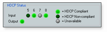
  1. From the View menu in DSP Configurator, select Video I/O to open the Video I/O workspace. Alternatively, you press <F4>, or click Video I/O in the Legend section of another workspace.

  2. Double-click the MTP block on the output side. The Output MTP Settings dialog opens.

  3. Select the Pre-peak check box to enable pre-peaking. To disable pre-peaking, clear the check box.

HDCP Compliance

The Audio & Video I/O workspace and the Video I/O workspace show an HDCP status indicator section. HDCP status is derived from the digital input signal or digital output signal.  

The HDCP Status section of the workspace is enabled while in Live mode and displays the following details:
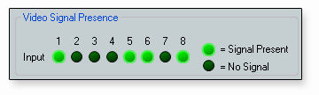
  • If an HDCP-compliant source is detected on the inputs, the indicator for the associated inputs are shaded light green.

  • If the active source is HDCP-compliant and the connected display is non-HDCP compliant, the output indicator is shaded dark green. If the connected display, is not HDCP compliant, the MLS 608 D Series device mutes the output.

  • If the HDCP status is not available, the associated indicator is not shaded.

Video Signal Presence

The Audio & Video I/O workspace and the Video I/O workspace show a Video Signal Presence indicator section. This section of the workspace is enabled while in Live mode and displays the following details:

  • If a video signal is present on one of the eight inputs, the associated indicator is shaded light green.

  • If no video signal is present, the associated indicator is shaded dark green.